Live devices | All devices | Fields | About | Test log | Admin Login
About
Background
Moisture Device
This device has been developed to monitor conditions near trees to alert tree carers of exceptional conditions and to aid in research into different soil conditions and mulching and watering strategies. Developmnent has been supported by Earthwatch UK where the sensor is being tested for use in Tiny Forests.
Each device monitors the soil moisture, soil temperature and air temperature and reports this and system data every 2 hours via the mobile phone network to a server.

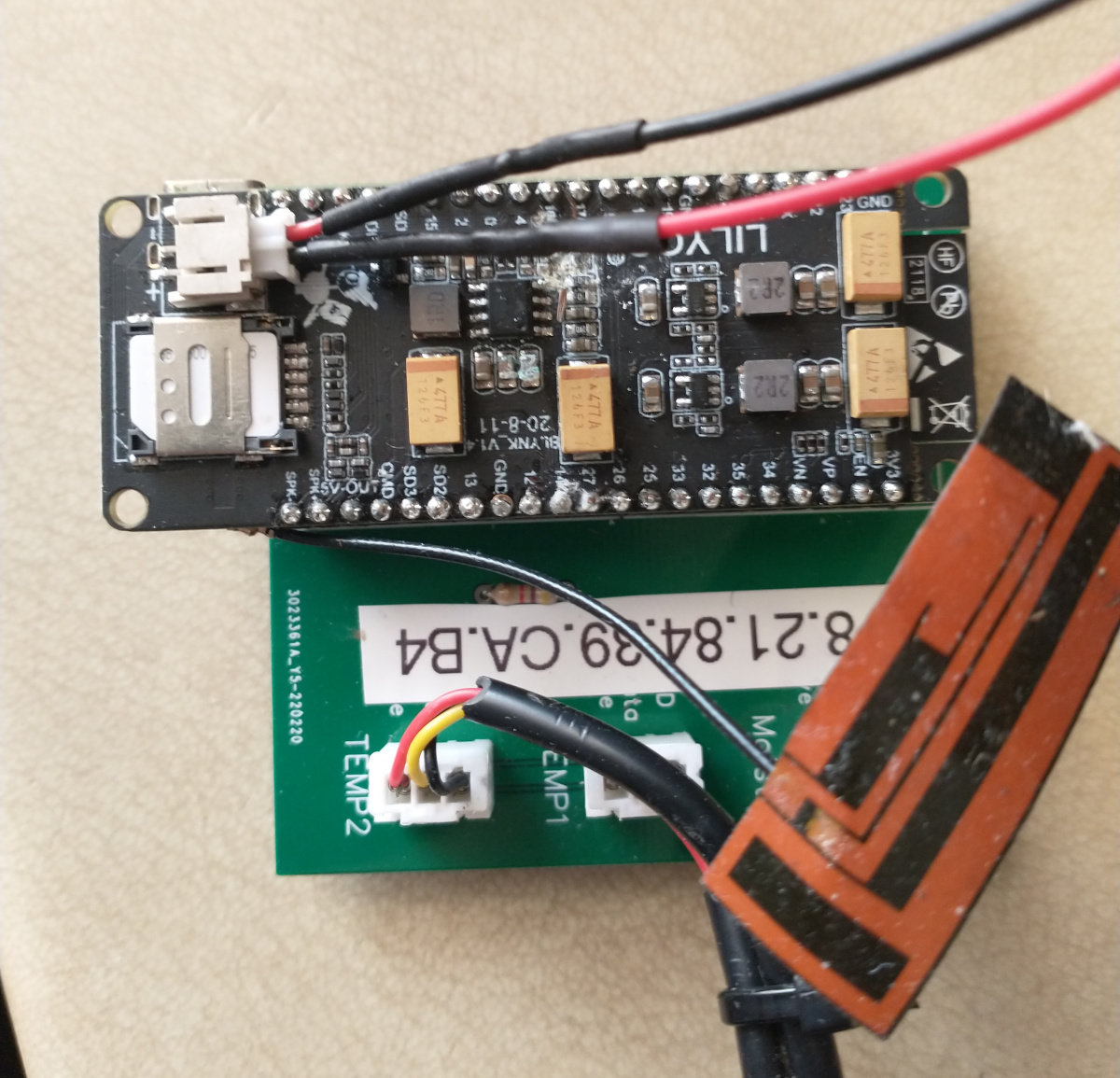
The heart of the device is the board carrying the microcomputer (underneath) and sockets for the battery pack and the SIM card holder

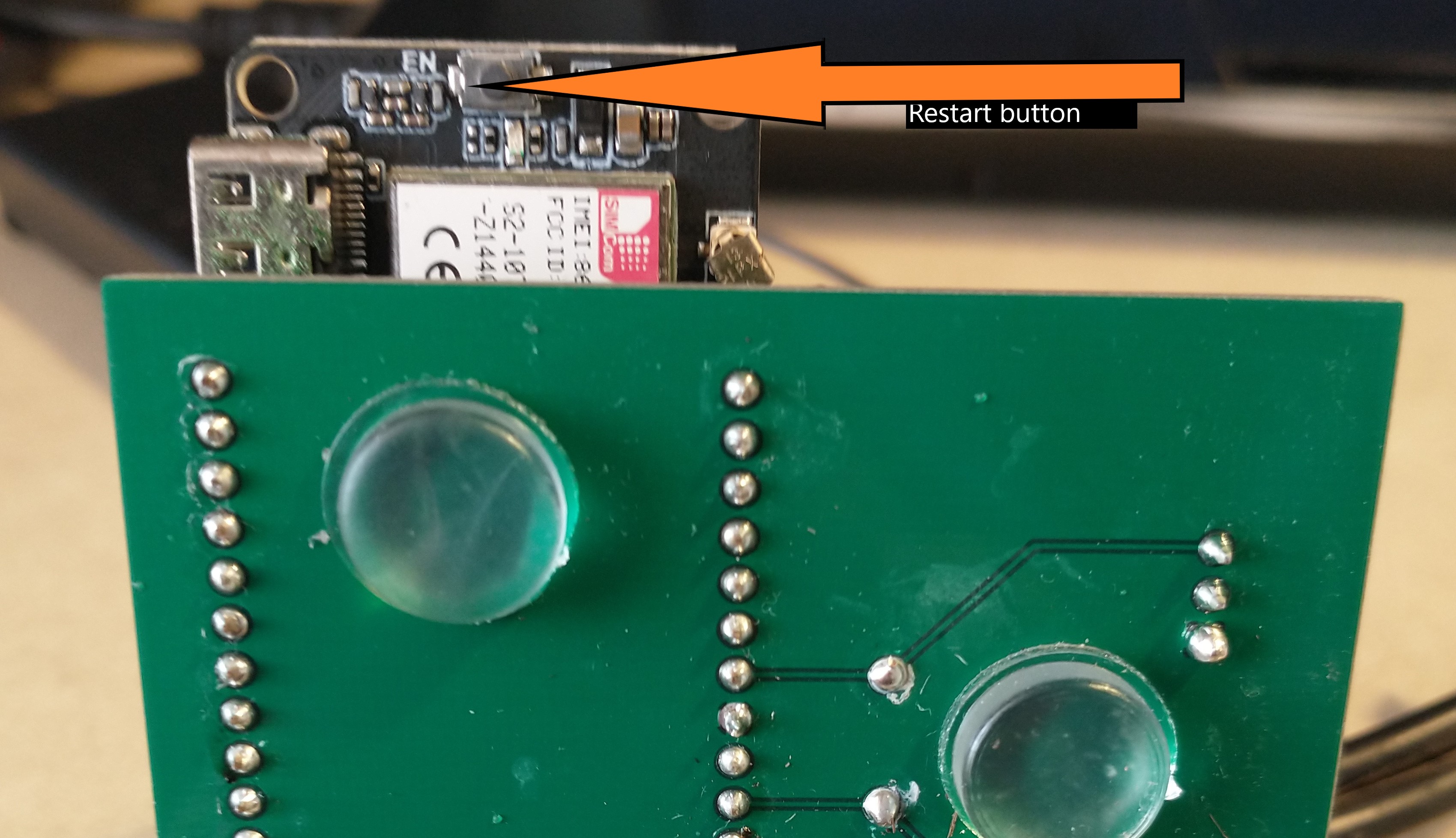
To restart the device you need to press the reset button which is under the left hand end which sticks out.

Field Installation
- check that the batteries are fully charged and that the battery box is plugged in
- check that a ThingsMobile SIM card is installed
- attach the air temperature sensor (long lead) directly to a tree or stick with tape . Sensor should be 1 foot above ground and unshaded
- near the tree, in the zone where water would be applied , use a trowel to dig a 6in deep slot.
- place the moisture sensor point first into the slot so that it is covered
- place the soil temp sensor (short lead) at the bottom of the slot , away from the moisture sensor.
- cover the slot and compact the soil.
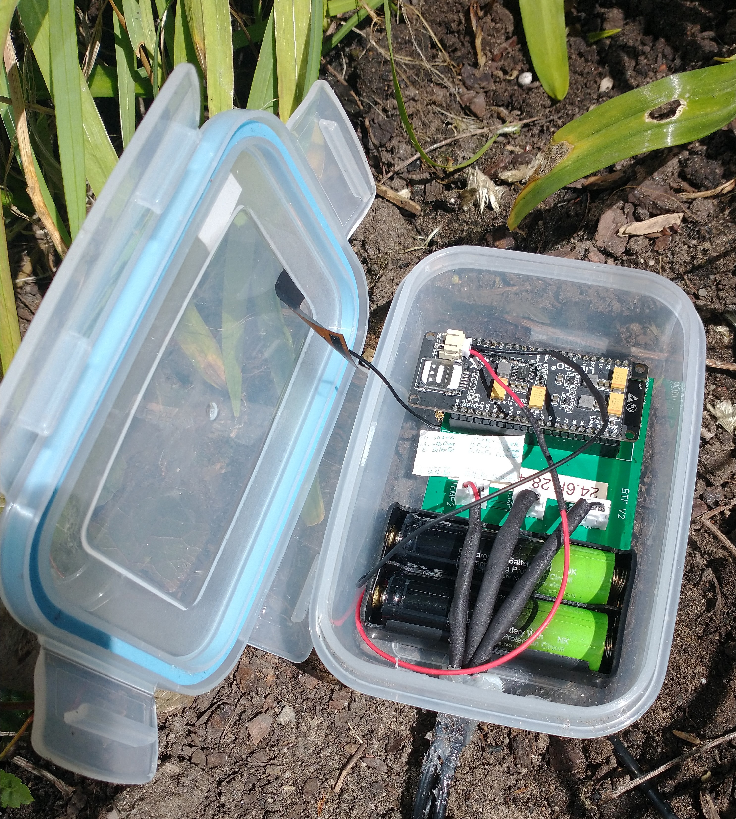
- lightly cover the device box with mulch. The GPRS aerial is attached to the underside of the lid and needs a view of the sky
- The device starts up with 6 test reports every 30 seconds. These reports are directed to a test log from where they can be viewed on a mobile phone with View test log. This enables the moisture readings and temperature sensors to be checked before installation. Any changes needed can be made through the dashboard editor (below). This script also checks that the usual cycle of deep-sleep and communication via GSM is functioning.
- The test log viewer shows an index of devices. The one of interest to us is the one whose MAC number is attached to the device. Select the page for this MAC address or wait until it appears.
- briefly press the black button underneath the board to start it (HARD RESET). After a few seconds the red LEDs should flash
- As the device starts to send reports, the page for that MAC address will show the data as it arrives. Check that all readings are within range.
- The test sequence will restart if the device is restarted by pressing the small black button.
- after 6 reports, the next report will be a real data reading and will appear in the device page on the dashboard provided the device is active( set in the dashboard). The data won't be graphed until there are a few data points buth the data view will show the data being gathered.

Maintenance Tasks
Battery Change
- open the device box - take care if the aerial is attached to the lid
- check for any damp - if any, clean the inside and the board and replace the silica sachets
- remove the two batteries - a small screwdriver helps to ease them out. Note the orientation of the batteries - the two batteries are used in parallel so that the output voltage is the battery voltage, 4.2v. Sometimes the markings on the battery box wrongly indicate that they are in series. If in doubt, the battery box spring goes on the base of the battery.
- replace with two fully charged batteries
- press the black reset button under the chip briefly. After a few seconds, the red leds will start flashing.
- replace the box, making sure that sensors have not been disturbed
- the device will make a few test reports (see Field Installation above) which can be monitored on a smartphone
Things Mobile Topup
ThingsMobile provides a single account from which small amounts are allocated to each SIM as the credit is used. Account access (CW) is needed to topup this account. Costs are currently E0.12 / Mb.
Configuration editing
Configuration file
Improvements in 2023-24
Hardware
Board failures have been traced to rusting pins and poor cable entry sealing:
- It is convenient to be able to plug and unplug a micro-processor chip but in practice these hardly ever fail, but the connection between the pins and the header socket has rusted. I now directly solder the processor to the PCB.
- The entry for the sensor cables has never been satisfactory. I have now designed a custom two-part gromet which is 3D printed in flexible TPU filament
Arduino device code
There was no association between a device and the SIM card it was using which is needed for accounting purposes. The current version of the code reports the SIM's CCID so that connection can be made. It also returns the version id.
Improvements in 2022
Arduino device code
The first version of the device code required an unique device Id to be included in the Arduino script. It also required minimum and maximum values for the moisture sensor since each sensor has a different range of values. These values are needed to calculculate a percentage moisture value. This meant that every device needed its own version of the script.
The new version (currently V6.6) uses the MAC address of the device as its ID. WiFi is an integral part of the ESP32 microprocessor and although it’s not used in this design, we can still access the MAC address and use that as an device identifier in reports. The calibration values are now held in the server configuration file for a device and moisture reading conversion to a percentage is now done on the server on receipt of the report. In addition the assignment of a sensor to a role (air , soil) is also done in the server configuration.
In the field it is useful to know that the device is running and to be able to recalibrate the moisture sensor and ensure the correct sensors are used for air and soil. Previously a separate script was used for calibration, but they are now combined into one common script. On startup after pressing the hard restart button, the boot no is reset to zero. For the first 6 cycles, the sleep time is reduced so that reports are generated every 30 seconds. These reports are flagged as test values and directed to a test log where they can be viewed live on a smartphone. This allows the moisture sensor to be read in the dry condition and then immersed in water to record these limit values. After these calibration reports, the sleep time is set to 120 minutes.
The current version is on GitHub
Server Code
The dashboard shows the data from all active devices. Other tabs show all devices and all fields. Admin users can start and stop logging, archive data, edit commonly edited fields and for more complex changes or to create a now device, can edit the XML configuration file for a device.
Device construction
PCB
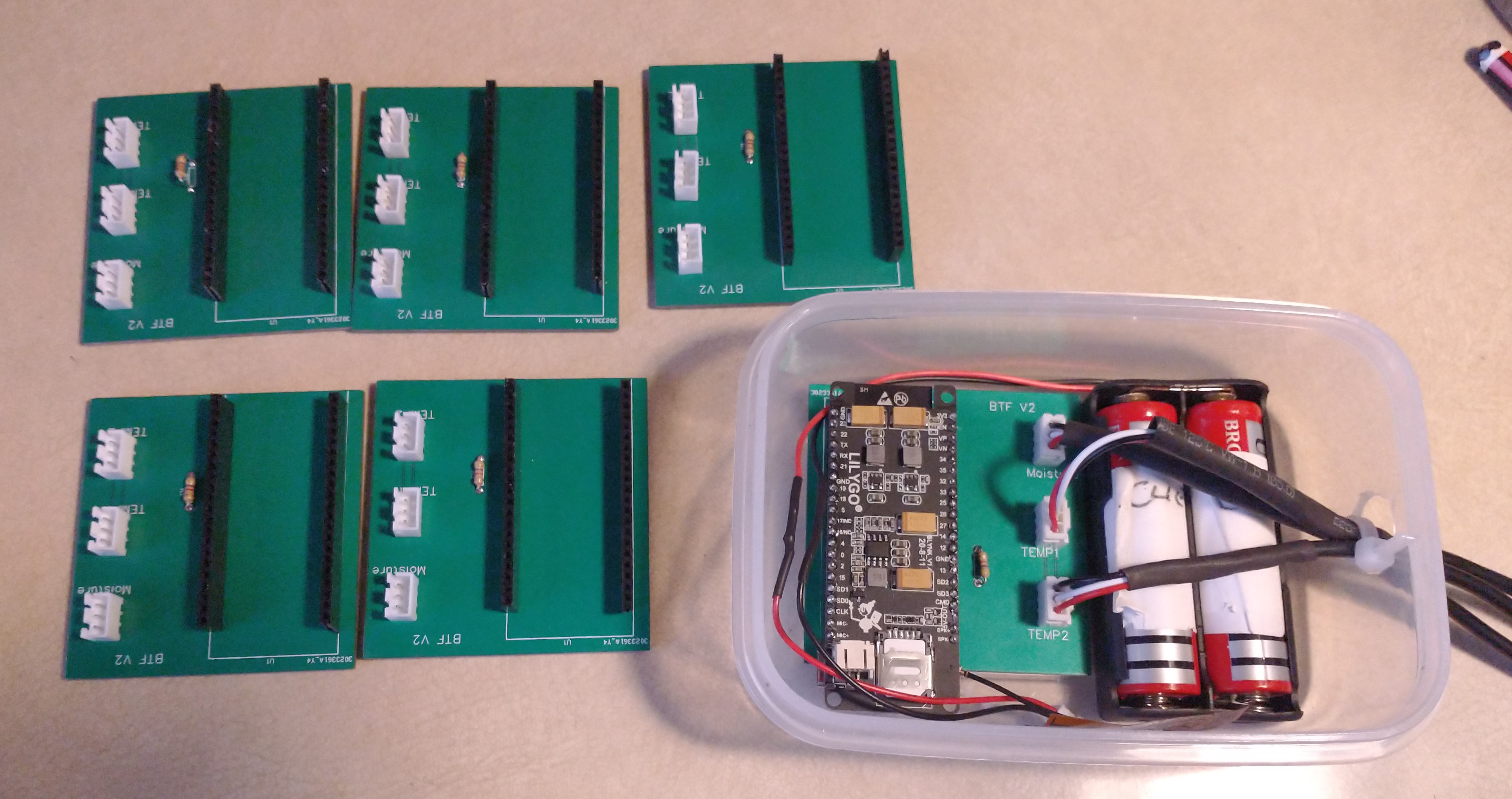
A custom PCB has now been created using EasyEDA and fabricated by JLCPCB. I’ve chosen to use JST XH-2.54 sockets on the board although the plugs are difficult to attach to the sensor leads. A batch of 6 devices is being made up for use by the science team at Earthwatch. A further batch of 10 boards with improved labelling is on order to replace our existing boards and for use by Bristol City Council.

Parts list
The full Bill of Materials can be found on Github (TBD)
Construction steps
The following show the steps required for a number of tasks required to construct a device.
TTGO boards
- clean with alcohol
- solder headers in modules with battery plug side up using board with a couple of socket strips in place to hold the headers.
- check joints carefully
JST plug assembly Temperature and moisture sensors plug into the PCB with JST plugs which need to be assembled. This requires :
- JST pins (in JST kit)
- 3 pin JST plugs
- SN-01BM cripping tool
- Trim the wires to about 2.5 mm. It's hard to do this exactly with a wire stripper, even an automatic stripper. I found it easier to strip longer than I needed and trim to length with scissors.
- It's fiddly to align the pin in the crimper (the smaller slot) but it gets easier
- Check that the crimp is well made before inserting into the socket.
- You can remove a pin from a socket by depressing the catch but its tricky
Temp sensors: 2 per device
- The two sensors have different lengths - short for the soil sensor, longer for the air temp sensor. This helps with installation and knowing which is which.
- install a JST plug with the correct pin orientation - looking from the catch side of the socket Left to Right: Ground/Data/Power
- fit in test rig and test
Moisture sensors: 1 per device
- Cut a 30mm wire from a section of 3-strand sensor cable
- add a JST plug with the wire order (from the catch side,Left to Right) : Data/Power/Ground
- Add a section of heat shrink to cover the wires.
- use a small cable tie to secure the plug to the socket on the moisture sensor
- add a JST plug to the other end with wire order (catch side,Left to Right): Ground/Data/Power
- use silicon sealant to cover the exposed electronics on the moisture sensor and around the plug
- test and calibrate the sensor
PCB assembly
- clean PCB with IsoPropanolAlcohol
- cut the socket strips to size and fit a TTGO board just to hold the headers at the right orientation
- turn upside down, hold the board in place with a bit of blue-tack and solder a few pins on the socket strips to the PCB. This ensures the headers are oriented to fit the board
- remove the TTGO board and solder the rest of of the pins. Ground pins take more heat.
- fit and solder the 4K7 resistor and trim the leads
- fit the JST sockets using a bit of blue-tack to hold each socket in position. Ensure the JST sockets are fully down to the PCB and with the slots on the socket pointing outwards
- Refit the TTGO board and check continuity:
- JST pins for all sensors are : GND;Data;Power (labeled on latest PCB)
- Board Pins are
- Gnd to sensor Gnds
- VP to moisture data
- 25 to moisture power
- 14 to temp data(both)
- 13 to temp power both
Device assembly and configuration
- fit the ESP32 board to the PCB, aligned with the white line at the back edge of the board.
- fit two temp sensors and one moisture sensor
- Plug the device into a USB port and start Arduino
- install moisture-sensor-power-on-test.ino (source)
- Start the Montitor
- check that test reports are appearing on the monitor
- check voltages at the pins are as expected
- note the MAC address
- put the mosture sensor in water and note the water reading; then dry thoroughly and take the air reading
- note which sensor is used for which role by warming one in your hand
- check that the battery voltage is as expected
- create a label with the MAC address and stick on the board
GSM script installation and testing
This script will test the GSM connection to the server and deep sleep- fit ThingsMobile SIM
- plug in the battery container with 2 fully-charged 18650 batteries
- plug the board into a USB port
- Install the latest production script (V6.6)
- Start the monitor
- Also open the Test Log Viewer which can also be used on a smartphone in the field
- The warmup phase will run through the reporting cycle 6 times in 3 minutes: collect data, connect to the server via GSM , send the data and go into deep sleep
- Reports should appear on the Test log Viewer with more detail shown on the Arduino monitor - check that the device is working correctly when on USB power.
- When all is well, unplug the USB power. If necessary, restart the device by pressing the black button under the board to restart the warmup cycle.
- Check in the Test Log Viewer that the device is working as expected on battery power.
Container assembly
- Use a 450 ml Clip & Close container
- Drill a 13mm hole in one end, below where the clip will be
- Place the device at the opposite end to the whole and the battery compartment in front of it
- Lead the sensor plugs through the hole. The moisture sensor is too big to go through but the hole is big enough for a JST plug.
- Use silicon sealant to fill the hole
- Place the patch aerial on the side of the container or on the lid
- add a few silica bags to help keep the inside dry
Server configuration
- login as an admin user
- download a similar device as a base configuration
- edit the MAC address to the value on the device
- other fields can be edited once the configuration file is uploaded
- upload the configuration as a new device
Fault fixing
- If no signal can be obtained, or the aerial is damaged or disconnected, the device will retry every 30 seconds. This may mean that the batteries become exhausted quite quickly and wilneed replacing.
Work to do
HardwareI have a concern that the batteries are not lasting so long after a few recharges. Since the batteries are only replaced when the server has stopped, the batteries may be being discharged too deeply which is reducing the ability to be recharged. It may be preferable to change batteries every month.
Dashboard
- user selection of graph time span
- graphing the archived data